Asian Fusion Handplane – FineWoodworking
In April 2024, I attended Fine Woodworking New England at the Connecticut Valley School of Woodworking. At the event, I sat in on Andrew Hunter’s Japanese handplane presentation. Andrew is a devotee of Japanese tools and called out several shortcomings of Western planes. His primary point (as I took it) was that a Japanese plane’s cutter sits at roughly 2/3 of the way BACK from the front of the plane, giving it a very stable lead into the cut. A Western plane’s cutter sits roughly ¼ of the way from the FRONT of the plane, and starting a cut requires pushing forward on the heavy rear portion of the plane while only 1/4 of the plane is balanced on the surface of the workpiece. To add another variable, it is that front 1/4 of the plane that is most susceptible to wear.
Later we chatted about how such changes might come to pass. Being a tool maker, I had ideas. Along the way, Andrew said “You should make that.” In the end, I decided to give it a go. Thanks to Fine Woodworking for posting videos of the presentation. It made it easy to go back and take notes. The whole event was awesome.
 |
 |
The changes included moving the cutter to the rear of the plane, bedding the blade at 39° instead of 45°, and sharpening at 28°. My proof of concept started with a $3 garage sale find; a Stanley #24 burner (transitional), bought just for the iron. The #24’s metal parts would be the basis for the new plane. I sharpened and tuned it to make sure it would take a shaving, then tore it down. I used the donor body as a pattern to cut the complex mortise for the re-mount on a ramped plane body in Douglas fir and the results were excellent. It took super fine shavings and got a glassy surface on white pine and cherry. I have to recommend against using doug-fir for a hand plane based on the splinter risk!
What follows is a step-by-step guide to building Stan Li, the Asian Fusion Handplane.
I “won” a lightly restored Stanley # 27½ from an online auction site for about $20. The “restoration” of the body looked to be done with a belt sander, but it was going into the fire anyway. Again, I sharpened & tuned it to make sure the guts of my build worked in their original form. Don’t skip this! You’ll need a sharp blade later on, and finding out it works provides peace of mind for the effort you’re about to put in.
 |
 |
Tear down your donor plane, taking notes and photos as you go. Pay attention to the position of the frame relative to the mortise and trace it on the body before you unscrew it, it will help later. You’ll be duplicating the mortise from the donor plane with one change; a tighter throat. My 27 ½ had a 45° bed and a 10° throat, with a 15° wear at the base. The bed and throat projected to intersect just above the sole, with the wear serving to open up the mouth (fig. 1 below). The wear and mouth will be opened slowly once the iron can be set in the body as a guide.
The mortise also had a notch to accept the casting’s extension for the cap screw. ¾ in. back from the bed, there were 2 brass threaded inserts for the frog screws. This is one place where Stanley decided not to reinvent the wheel. The inserts and screws were a loose-fitting 1/4-20. Three screws were holding the frame to the body—one behind the tote, one through the knob, and one just in front of the mouth mortise. The donor body came in at 15 in. x 3 in. x 1-3/4 in.
Start with a blank that is the proper width, but thicker than the Donor. My 3-1/2 x 3-1/2 x 18 in. Q-sawn hard maple block was purchased as a 36” baseball bat turning blank on ebay from MoBat Company. They sell as 3 in. x 3 in., but they come in heavy. I dressed it down to 3 x 2-1/4 in., with the quarter-sawn grain lines running across the 3-in. measurement on the end of the blank in order to keep changes in thickness to a minimum. I let it sit in the shop for a few weeks and it stayed straight and true.
Cut your Iron frame down as much as you dare—I lost about 5 in. I deleted the rear section for the tote, then drilled a hole and filed a flat to use the knob at the rear. For now, drill a 1/8-in. hole that will become a pilot hole for the knob screw. Do this at the drill press for accurate placement. At the front, I removed the seat for the front knob. There’s a screw hole that remained just in front of the frame opening that I’ll use for final assembly.
 |
 |
The critical measurement to get the new plane to function is the thickness of the body at 90° to the frame at the mouth as measured from the donor plane. The new block is thicker because we will cut a 6° ramp at the rear of the plane to lower our bed angle to 39°. (The tote won’t be comfy at this angle) Cut the ramp using a tapering technique on the jointer. Make a test taper using some scrap and count your passes. As you approach 6° slow down and go 1 pass at a time. I took 9 passes, measured using a Wixey digital angle gauge and landed at 6.01°. A final pass without the backstop cleaned up the small snipe at the front without changing the ramp angle.
After determining the position of the frame on the ramp and cutting the mortise, you’ll use light passes on the jointer to mill the sole of the plane “up” to the mouth at 1 3/4 in. below the ramp surface. Resist the temptation to slide the frame down to where you won’t have to mill the sole. Tearing out the sole at the mouth is a far worse and more probable result. Don’t ask me how I know this. The jointer also opens the mouth slightly with each pass as the bed and the wear grow further apart and it is a controlled way of tuning the mouth.
Position the cut-down frame on the ramp and tape it in place. Using the donor body as a pattern lay out your mortise on the side of the ramp and make sure you have enough meat below where the mouth will land. Once you’re sure, screw it in place. Use undersized or short screws now so you’ll have solid meat later for permanent mounting. Trace the frame on the ramp and remove it, then use the donor body as a guide to lay out your mortise for the bed and throat. Don’t worry about the wear yet. Remember to use only the ramp as a reference surface.
 |
 |
Start by chopping out “inside” the mortise leaving about 1/8 in. in all directions to avoid splitting during the quick heavy chopping. You can drill out waste to the extent that you are comfortable or even use a hollow chisel mortiser if you are so equipped. Slow down and approach your layout lines. Stay inside the lines for now (leave the lines just visible on the surface). Cleanup and refinement will get you there later… avoid going over.
Refine the bed with chisels. As you get deeper put a solid straightedge across the mortise to reference a combo square and pare down to 45°. Widen the bed until your plane iron fits with about 1/16” to either side… it should be close to your layout lines. Don’t try to perfect the Bbed yet, move on to the sides and the throat. Your depth at this point should be short of the full thickness of your donor body. The added depth will come from extending the bed to meet the wear.
 |
 |
Take a small, flat block of something (I used aluminum) and refine surface on something flat like your tablesaw with sandpaper on it. I drilled a hole for my fingser to grip into. Dirty up the sanded surface with a pencil and rub it on the bed. The dirty parts of the bed are high spots that need to be pared away. Remove the pencil marks with a chisel, rub again, remove the high spots, and repeat until you get a uniform dirty surface when you rub the Bed, which is now flat. Double-check that you’re still at 45°, get back to it if you’re not.
 |
 |
Once the Throat and the Bed are meeting at the bottom, establish a line for the Wear. Use a cutting or wheel gauge to hit the point of the Wear on the donor block. Transfer the mark firmly onto the throat of the new body. Cover the inside of the throat with green painters’ tape and mark it again, then peel the tape below the mark. This will be the upper landing of the Wear. Transfer the mark up and around the body until you hit your layout lines on the sides. Measure the angle of the wear on the donor and lay it out on the new plane. Mark the line fully across the side of the plane so you can use it as a visual reference for holding your chisel.
Clamp the body to your benchtop. You still have meat below where you’ll be chopping to so there’s no need to worry about blowing through to your bench. Begin chopping the Wear down to the Bed, then extend the Bed to the Wear and repeat until the Wear angle is correct and the bed has been extended to meet it. You should still be well above the bottom of the plane body.
 |
 |
To lay out the notch for the cap screw tongue carefully lay a strip of green tape on the donor body right up to the line of the Bed. Flap the ends for easy peeling and secure it around the edges to the sides. Mark the corners/ edges with a pencil. Rub a pencil on some scrap and get a fingertip filthy. Rub the finger on the taped surface to get the positions of the notch and any screw holes. Take the tape off carefully and transfer it to the new plane body. Centerpunch the screw holes and chop the notch right through the tape.
 |
 |
At the drill press, level the ramp relative to the quill and drill small pilot holes in your punch marks. If your frog was held to your donor body with wood screws follow up with the appropriate pilot hole for those screws. Measure how much your screws will extend into the body, especially at the rear of the plane. Not all of that meat will be there after you mill the sole back up to open the mouth. In my case, I needed to add threaded inserts for machine screws. I used a 3/8” forstner bit and set the depth to just below the surface of the ramp. I tested the drill and insert on scrap, close to an edge and end to make sure I was not going to split anything. The fun part of woodworking is that there is always a last-second opportunity to ruin something you have a bunch of time and effort in! The inserts were seated with a hex bolt and a hammer. Now it’s time to fit the frame & frog.
Using short screws to leave a bit of undisturbed meat in the body block for final assembly, mount the frame to the ramp. If all went well the outside tracing should be dead on. Add the frog and line it up with the Bed. Drop in your iron assembly. It should land at a point where you can just about run the iron advance up and into the chipbreaker slot. Take out the iron and head to the jointer.
 |
 |
Set the jointer for the lightest cut possible and go to work. Hold the body up to the light to see when you’re getting close. My jointer has a segmented cutter and unfortunately leaves slight scallops so I alternate feed directions between passes. On the final passes, feed the plane into the cutter so it won’t tear out the leading edge of the bed. When the mouth becomes translucent you are close. Get the mouth open and re-fit the iron and lever cap. The mouth will be too tight. Remove the cutter and take another pass or two… re-fit, repeat. When you think you’re there try to take a shaving.
 |
 |
My first shaving choked at the mouth so I went back to the jointer for another pass. Second and third were the same. My fourth shaving came off perfectly straight, an indicator that the chipbreaker was not engaging the shaving, the cut was also a bit dished. The culprit was a slight bulge just behind the mouth where the iron and lever cap applied pressure. I used a chisel to trim away the bulge with the blade assembly installed. I took another pass, the shaving was perfect and the planed surface was glassy & beautiful. The plane pushes easily and pulls as well. I have limited experience on the pull side so I’m looking forward to getting it into the hands of someone like Andrew.
 |
 |
With the function close, turn to the finishing. Remove the frame and clean up the surfaces. I had to scrape the top, ramp, and sole to remove jointer marks. I chamfered corners, cleaned up the end grain, and added grip grooves on the sides. A light sanding on all but the sole and a wipe of sealcoat finished the job.
After 35 years in architectural photography, Myko now works as a consultant, employing the same skill set toward environmental compliance. He holds three U.S. patents and is the inventor and manufacturer of Tailspin Collinear Marking Tools. A woodworker of 50 years, he got started with an X-Acto carving set and a block of balsa on his 10th birthday and just kept going.
Fine Woodworking Recommended Products
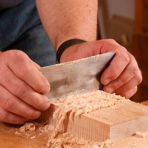
Bahco 6-Inch Card Scraper
The size and thickness are what matter here. A consistent performer, this Bahco scraper is found in many shops we visit.
Stanley Powerlock 16-ft. tape measure
With its smooth lock, tough case, compact size, and excellent accuracy, this Stanley tape is perfect for workshop use.
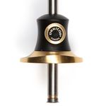
Veritas Micro-Adjust Wheel Marking Gauge
The adjuster runs through the beam from a small knob at the back end right to the cutting wheel, which moves in and out as you turn the knob. This arrangement works well but makes adjustments a two-handed operation, requiring a little more effort.
Sign up for eletters today and get the latest techniques and how-to from Fine Woodworking, plus special offers.
