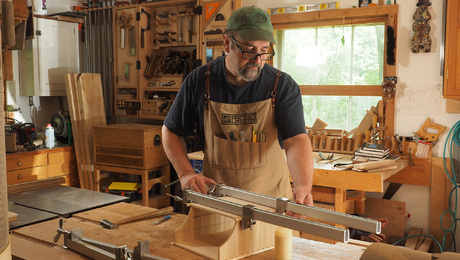
The Helix Table: A piece with multiple personalities
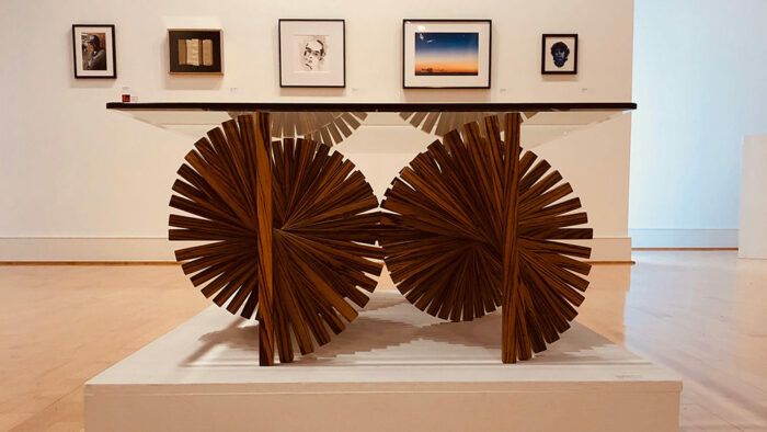
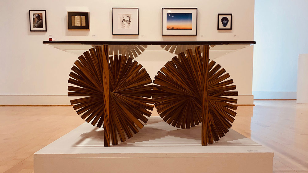
The Helix Table is an example of how a common shape in nature, the spiral, might be applied to furniture design. There are three features of the table that I hope will spark your interest and perhaps your appreciation. First, it has a unique architectural form. Most table bases are rectilinear.
This table base is in the form of two neighboring helices or spirals. Second, the construction processes are not obvious. How does one get all those staves to assume that spiral shape? Finally, this table format provides a surprisingly rich set of aesthetic options in use.
Unique architectural form
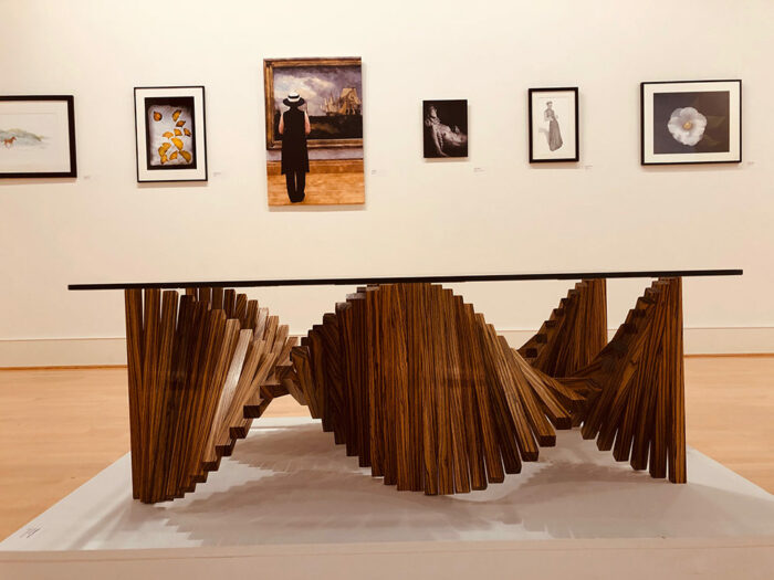
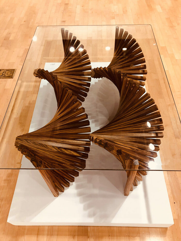
The common prototype of a table is a rectilinear form consisting of three or four corner legs supporting a top that is frequently opaque, concealing much of the base. The Helix Table features a glass top, to increase the visibility of the double helix base. The base is composed of two separate units.
The units are contiguous with one another at a midline cutting the long side of the tabletop in half. There are 8 vertical staves, one on the corner of each base unit, holding up the tabletop. So there are 8 straight, vertical legs! Nevertheless, the predominant perceptual feature of the base, from just about any angle, is its sinuous curvilinearity.
What is also clearly visible is that there are no curved elements in the piece. The curves are created in the viewer’s mind’s eye by a series of straight staves joined to one another at the midpoint. The end staves in each unit are plumb to the ground; and there is a constant, increasing angle from one stave to the next.
While the staves are straight, they follow a discrete but circuitous route that the eye smooths out, bringing the viewer to “see” sinuous curves. Indeed, the idea of using straight sticks to produce spirals is what seduced me into doing this project.
Construction processes
The idea of joining discrete, linear elements together to suggest a curve is not new. However, the idea of using the approach as a table was new to me. And as I picked up the gauntlet several challenges became immediately apparent.
First, there need to be enough “steps” so that one’s eye fills in the curve and not so many steps that there is only a trivial amount of curve to fill in. I opted for 10 staves per 90° of arc. [See Footnote 1.] This seems to provide enough of a suggestion to enable the eye to do its work without the design appearing too “jumpy.”
The next question a maker must ask is how might the staves be joined together. The joinery must solve two alignment problems: The center point of each of the staves must be coincident and the angle between them must be 9°. I made a jig that indexes the ends of two staves and holds them at the target angle with midpoints coincident. The jig allows gluing only one joint at a time. So, the base is built up of pairs, then the joining of two pairs to make a quartet, and so on.
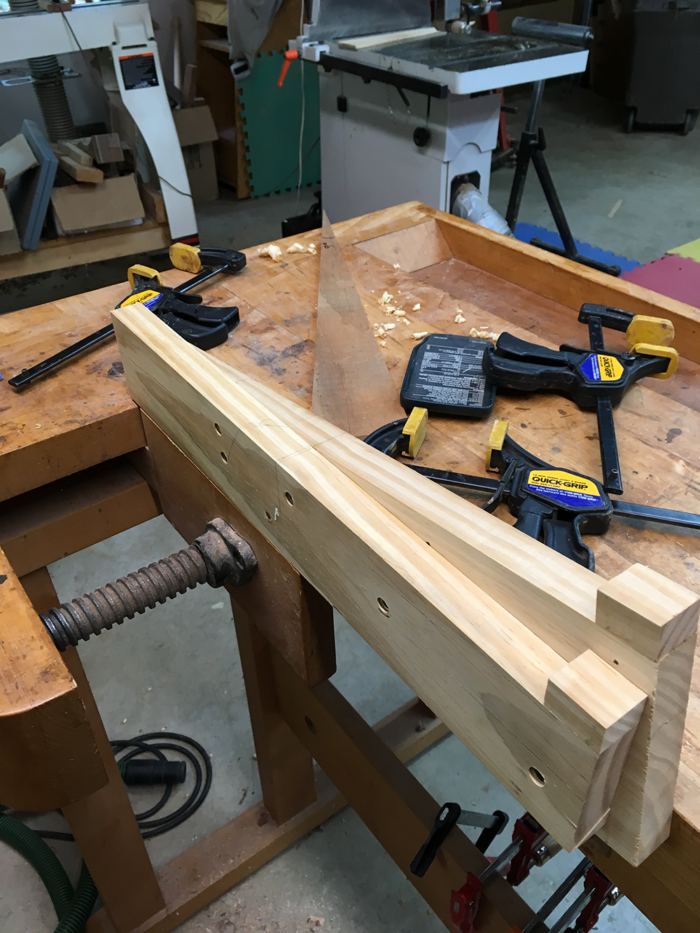
Jig for holding two staves at 9° to one another and with centers coincident. Photos by A. Tesser. |
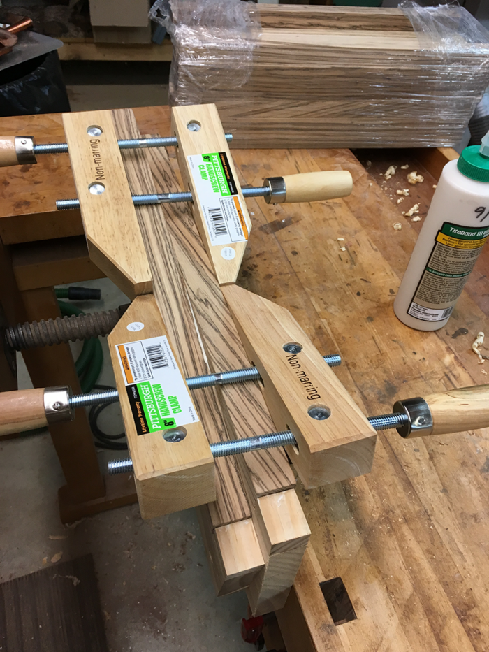
Two staves being glued together |
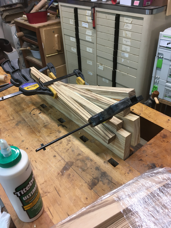
Gluing two pairs |
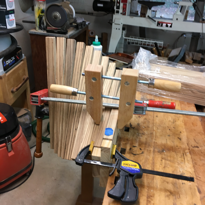
Gluing the 10th stave to a set of nine |
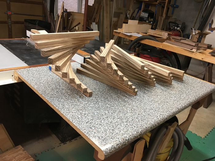
Growing sets of staves, mid-process |
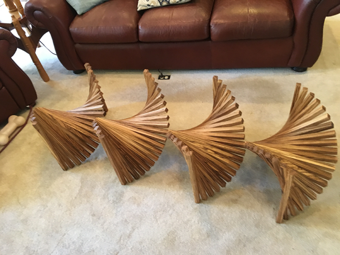
This process continues until I have two sets of 10 staves each. Recall that each base unit consists of two, side by side, 180° sweeps. The two sets are clamped next to each other on a “ground” surface with an end stave in each set being held vertically, like a table leg. With the set held like this, the second stave is at 99° concerning the ground, the third is at 108° .. . and the tenth is at 171°. The next element in the series should be at 180° or perfectly horizontal. This is where the “spine” comes in.
The spine is twice the length of the staves. It is glued across both sets of 10 staves and holds them together. Indeed the spine is the only thing holding the two sides together. The spine also helps clean up errors. Regardless of how accurate the gluing jig is, whatever error exists is multiplied by 9, the number of joints holding the 10 staves.
The jig is not used to glue the spine. Just as the “legs” are clamped in a perfectly vertical position the spine is clamped in a perfectly horizontal orientation at a height making the midpoint of the spine and the midpoint “leg” coincident. [See Footnote 2.]
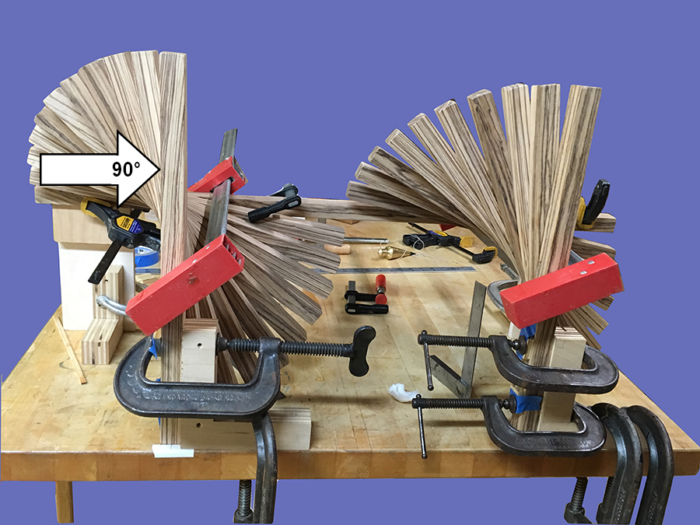
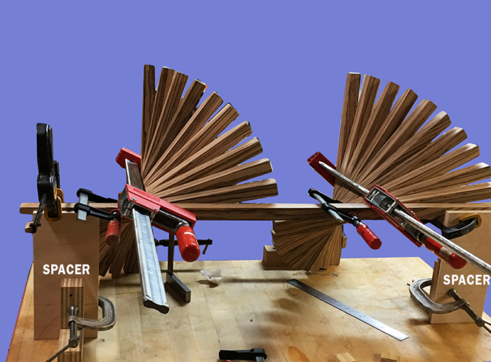
Gluing the spine in place completes one-half of a unit. To complete one full base unit, two more sets of 10 staves each need to be glued to the other side of the spine. It is kind of a docking operation. Everything must be held precisely in place.
The spacers hold the spine in place; each set of staves is aligned with the spine; and each of the four end staves is clamped plumb. Now, I take two or three deep breaths, apply glue and clamps to hold everything together, and then pray.
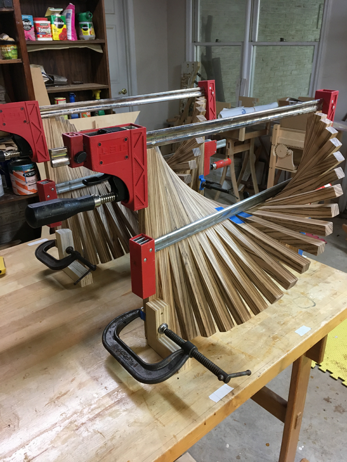
There are many, many joints. So, there is tedium and lots of opportunities for error. But there is also joy (relief?) in watching the piece grow as the pairs are glued to one another creating sections that come together until each base section is complete.
Aesthetic options
Although I had a particular vision in mind when designing and building this piece, I later discovered that it is endowed with intriguing flexibility. Indeed, I now think that its flexibility is one of its greatest strengths.
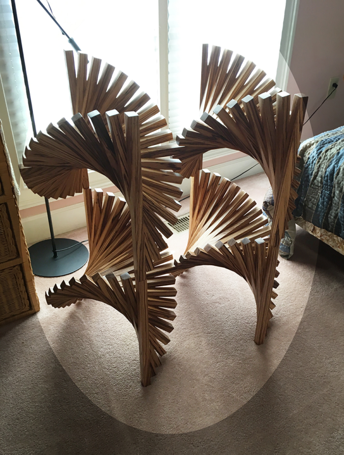
The original orientation (see photos 1-3) is what I envisioned when building the table. The base appears to be a single unit with a continuous waveform across the horizontal axis. Each of the bases can be turned 90° onto its side so that the legs are no longer vertical but horizontal. Now the spirals are in an interesting vertical spiral orientation.
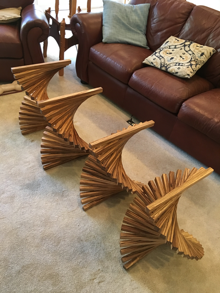
The bases can be configured in a Cross-Spiral Orientation. In the original orientation, the spines are separate and run from front to back through the depth of the table. In the cross-spiral orientation, each base is twisted a quarter turn so that the spines are contiguous and they appear to run through the center from one end to the other. It produces an interesting series of scallop shapes.
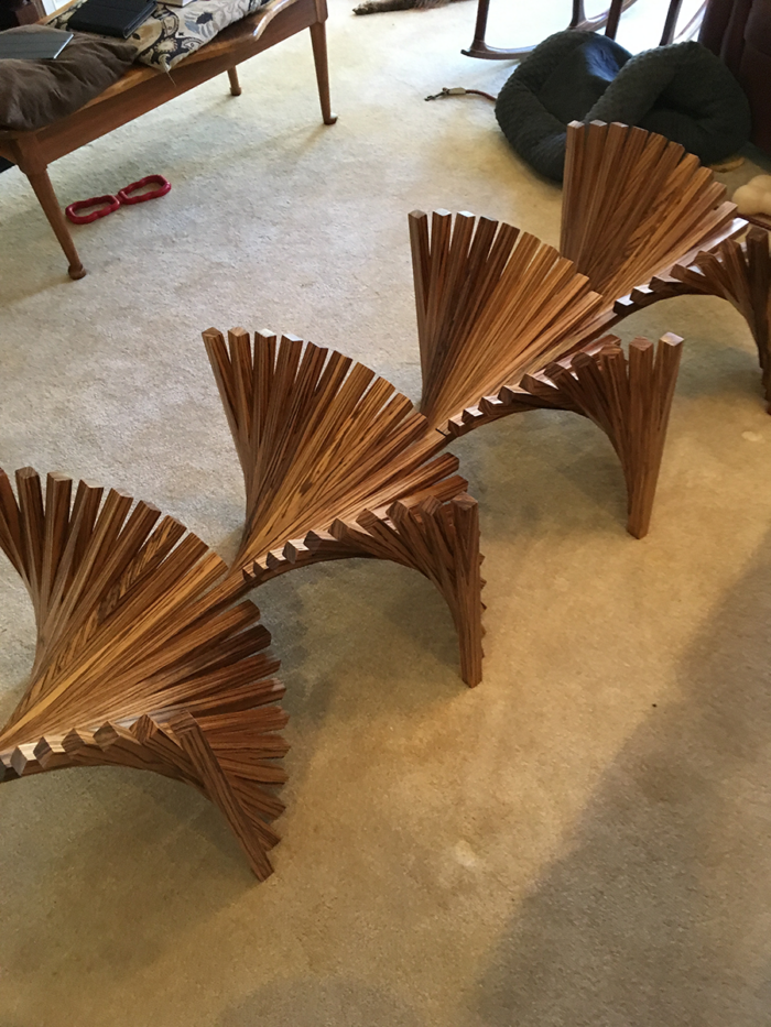
The two bases can also be stacked. Although the height is impractical for a table, I find the sculptural aspects of the Stacked Orientation attractive.
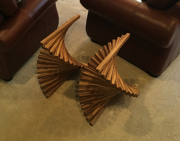
As frequently noted, the table has two base units. They can be separated and each base unit becomes a low single table base. Or, they can be separated and used as matched end table bases.
Summary
The helix or spiral is abundant in nature but certainly less so in furniture design. Our materials generally come to us in a rectilinear format and our tools thrive on straight lines and right angles. The Helix Table provides an example of the use of rectilinear materials to suggest spiral shapes that the viewer’s eye smooths out into sinuous curves.
The procedures outlined here for fabricating a Helix base are sometimes tedious and awkward and invite improvement. Nevertheless, there is a certain delight in watching each unit “grow.” Perhaps the biggest surprise and the greatest source of joy was the discovery of the multiple personalities the table could take on:
By turning each base unit 90° (cross-spiral orientation); upending each base (vertical spiral orientation); stacking the units; or simply separating the base units.
If you’re interested in exploring these orientations, watch this short video:
Footnotes
- The choice of 10 staves for each 90° of arc also fixes several other design parameters. The curve on each unit sweeps 180° on each of the two sides. So, 20 staves are needed for each side. The angle between each stave is 9°. Each of the regular staves was 1” X 1 1/16” (w) X 17.5” (H). Since there are 20 staves, and one spine (also 1 1/16”) in a sweep, each base unit is 21 5/16” long. Since each stave is 17 ½” long the height of each unit is 17 ½” (when the stave is in the upright position, i.e., the four corners). And each unit is 35” deep_recall that there are two side sweeps (each 17.5” wide) joined in the middle by a horizontal spine, 1” X 1 1/16” X 35” (the length of two horizontal staves).
- When the staves are placed on the jig at different angles their midpoints move in different directions concerning the midpoint on the jig. This difference is accounted for in the placement of the stops on the jig.
Sign up for eletters today and get the latest techniques and how-to from Fine Woodworking, plus special offers.
